39 electric motor diagram with labels
Parts of Motor, Working of Electric Motor & Uses - BYJUS Take two bar magnets and keep the poles facing each other with a small space in between. Now, take a small length of a conducting wire and make a loop. Keep this loop in between the space between the magnets such that it is still within the sphere of influence of the magnets. Now for the last bit. Connect the ends of the loop to battery terminals. Draw a labelled diagram of an electric motor ... - Sarthaks eConnect Working of Electric Motor Current in the coil ABCD enters from the source battery through conducting brush X and flows back to the battery through brush Y. The current in arm AB of the coil flows from A to B. In arm CD it flows from C to D, that is, opposite to the direction of current through arm AB.
Electrical Diagrams and Schematics - Inst Tools They are wiring, schematic, and pictorial diagrams. The two most commonly used are the wiring diagram and the schematic diagram. The uses of these two types of diagrams are compared in Table 1. The pictorial diagram is usually not found in engineering applications for the reasons shown in the following example.
Electric motor diagram with labels
DC Motor Nameplate Details Explantion - Electrical4u Armature Voltage: 110 Volts. The rated armature voltage is 110 DC volts. More than 110 volts supply to the armature winding is not recommended. Duty is nothing but the operating hours of the DC motor. In this, S1 duty means we can run the motor for 365 days X 24 hours. here you can find the other motor duty operation. Electric Motor - Principle, Working, Diagram - teachoo Electric Motor consists of Rectangular Coil of Wire ABCD A strong horseshoe magnet (or 2 different magnets ) - If we take 2 magnets, North Pole of first magnet faces South Pole of Other Magnet, as shown in figure... The coil is placed perpendicular to the magnet as shown in figure The ends of coil are connected to split rings - P & Q › worksheets › ac-motorAC Motor Control Circuits Worksheet - AC Electric Circuits After the motor has had time to speed up, another set of “starter” contacts bypass line power around the resistors, directly to the motor windings. Draw a diagram showing how this could be done for a single-phase electric motor, using two starter contacts: “R” for “run” and “S” for “start”.
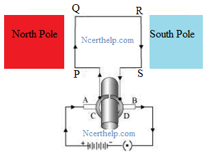
Electric motor diagram with labels. Electric motor Diagram | Quizlet The commutator is a broad ring of metal mounted on the axle at one end of the armature, and cut into an even number of separate bars (2 in a simple motor). Each opposite pairs of bars is connected to one set of coils. Electric Motor Nameplate Details Explained | Electric Motor ... Electric motors have a rated horsepower (HP) that is determined by the amount of torque they can produce at their running or baseline speed. The nameplate shown in Figure 1 indicates this motor is rated at 1 horsepower. The term "horsepower" comes from the rating of steam engines. Many years ago, James Watt invented the steam engine. Draw a labeled diagram of an electric motor. Explain its principle and ... Working of electric motor: As shown in the diagram, when a current is passed through the coil PQRS the coil starts rotating anti clockwise because a downward force acts on length PQ and at the same time an upward force acts on RS. Therefore, the coil rotates in anti clockwise direction. labeled diagram simple electric motor Electromagnet diagram draw physics labelled electromagnets magnet iron magnetic construction igcse field switch relay describe neat solenoid poles core coil. Motor control circuit diagram / start stop 3 wire control. Generator dc construction parts field magnetic main system diagram pole armature machine circuit globe commutator electrical ...
Electric Car Diagram - Car Construction Car Anatomy and Repair, Electric car, Engine, How a car Works, Construction. The active reference to source is obligatory if you use materials of a site Car Anatomy 886 shares › wiring-diagramEverything You Need to Know About Wiring Diagram - SmartDraw Unlike a pictorial diagram, a wiring diagram uses abstract or simplified shapes and lines to show components. Pictorial diagrams are often photos with labels or highly-detailed drawings of the physical components. Standard Wiring Diagram Symbols. Most symbols used on a wiring diagram look like abstract versions of the real objects they represent. Draw a neat diagram of electric motor and name the parts. Draw a neat diagram of electric motor and name the parts. Medium Solution Verified by Toppr The basic principle of an electric motor is that an electric current that is placed in a magnetic field will experience force. This is what is created and harnessed in an electric motor. The coil is used to carry the current and is usually bent into a loop. 7 Parts Of Simple Electric Motor And Function - AutoExpose This is the bacic principle of electric motors. When a magnetic rod is placed in a magnetic field it will produce a movement on the magnetic bar. The trunk, the magnet is placed on a pivot with the circuit in such a way that it can produce rotary motion when these two components interact. Electric Motor main Components 1. Stator Coil 2. Rotor Coil
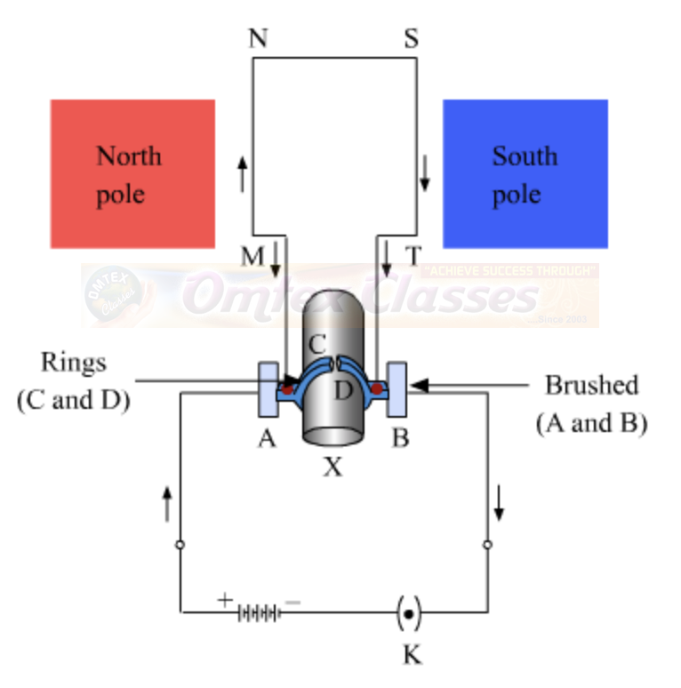
Question 11 Draw a labelled diagram of an electric motor ... - Byju's Principle: It works on the principle of the magnetic effect of current. A current-carrying coil rotates in a magnetic field. Working: When a current is allowed to flow through the coil MNST by closing the switch, the coil starts rotating anti-clockwise. This happens because a downward force acts on length MN and at the same time, an upward force acts on length ST. The picture shows a basic diagram of an electric motor. Which labels ... Armature is the rotating part of the electric motor or generator which contains coils of wire wounded over a metallic core. The commutator plays a crucial role in case of electric motor. The function of the commutator is to reverse the direction of current. The brush is the important part of an electric motor which is connected to the battery. Electric Motors: How to Read the Nameplate - WorldWide Electric The nameplate includes the based speed given in RPM. Base speed is where the motor develops rated horsepower at rated voltage and frequency. Base speed indicates how fast a fully-loaded output shaft will turn the connected equipment when proper voltage and frequency is applied. The sample motor has a base speed of 1185 RPM at 60 Hz. Electrical Symbols For Schematic Diagrams | EdrawMax Step 1: Launch EdrawMax on your computer. An extensive collection of electrical diagram templates can be found in the Electrical Engineering category. Click the icon of Basic Electrical to open the library that includes all symbols for making electrical diagrams. Step 2.1: As you are into the workspace of EdrawMax, drag the symbol that you need ...
Basic Simple Electric Motor Diagram | See More...
Electric Motor Diagrams - Mr. Electrician's Home Page A Split Phase Capacitor Start Electric Motor may be defined as a form of split-phase motor having a capacitor connected in series with the auxiliary winding. The auxiliary circuit is opened by the centrifugal switch when the motor reaches 70 to 80 percent of synchronous speed. Also known as a capacitor-start, induction-run motor.

Absolute Sewing Machine Information: November 2012
Draw a labelled circuit diagram of a simple electric motor and explain ... A commercial electric motor is one which uses the following (i) An electromagnet in place of permanent magnet. (ii) Large number of turns conducting wire in current carrying coil. (iii) A soft iron core on which the coil is wound. The combination of soft iron core and coil is an armature. It enhances the power of motor.

Patent US8269448 - Methods and systems for recording operating information of an electric motor ...
PDF Typical Electrical Drawing Symbols and Conventions. Basics 6 7.2 kV 3-Line Diagram : Basics 7 4.16 kV 3-Line Diagram : Basics 8 AOV Elementary & Block Diagram : Basics 9 4.16 kV Pump Schematic : Basics 10 480 V Pump Schematic : Basics 11 MOV Schematic (with Block included) Basics 12 12-/208 VAC Panel Diagram : Basics 13 Valve Limit Switch Legend : Basics 14 AOV Schematic (with Block included)
.PNG)
Electrical Circuits - Presentation Physics
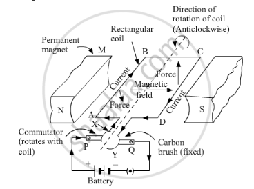
What is an Electric Motor? with the Help of a Labelled Diagram ... In an electric motor, a rectangular coil ABCD in placed between two magnets in poles N and S. Now, current is passed through it continuously. When current is passed into the coil, it produces a magnetic field around it. The two magnetic fields interact and cause the coil to rotate. When the coil rotates, the shaft attached to it also rotates.
What is an Electric Motor? with the Help of a Labelled Diagram, Describe the Working of a Simple ...
Basic wiring for motor control - Technical data guide | EEP Figure 1 - Typical Wiring Diagram Line diagrams show circuits of the operation of the controller Line diagrams, also called " schematic " or " elementary " diagrams, show the circuits which form the basic operation of the controller. They do not indicate the physical relationships of the various components in the controller.

Eventhough a little bit complicated for ordinary people to learn the electrical science, but ...
› worksheets › ac-motorAC Motor Control Circuits Worksheet - AC Electric Circuits After the motor has had time to speed up, another set of “starter” contacts bypass line power around the resistors, directly to the motor windings. Draw a diagram showing how this could be done for a single-phase electric motor, using two starter contacts: “R” for “run” and “S” for “start”.

Electric Vehicle News: February 2013
Electric Motor - Principle, Working, Diagram - teachoo Electric Motor consists of Rectangular Coil of Wire ABCD A strong horseshoe magnet (or 2 different magnets ) - If we take 2 magnets, North Pole of first magnet faces South Pole of Other Magnet, as shown in figure... The coil is placed perpendicular to the magnet as shown in figure The ends of coil are connected to split rings - P & Q

ELECTRICAL ENGINEERING AND PROJECTS: The electric motor:
DC Motor Nameplate Details Explantion - Electrical4u Armature Voltage: 110 Volts. The rated armature voltage is 110 DC volts. More than 110 volts supply to the armature winding is not recommended. Duty is nothing but the operating hours of the DC motor. In this, S1 duty means we can run the motor for 365 days X 24 hours. here you can find the other motor duty operation.

Project: Electric Booger: Motor Basics
Draw a labelled diagram of an electric motor, principle and worki

Washer Rama Museum.: MIELE AUTOMATIC 416S TIMER HOLZER MTA-469U SCHEMATIC DIAGRAM.

How do electric motors work? - Explain that Stuff
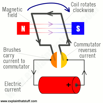
How do electric motors work? - Explain that Stuff

Inside an Electric Motor - How Electric Motors Work | HowStuffWorks
Three-Phase Transformer Mv DWG Block for AutoCAD • Designs CAD
Post a Comment for "39 electric motor diagram with labels"